Stage 7: Setup Views
Introduction
Key 3D uses ONE camera for still views. This is tied into Image Object functionality where images of people and trees and shrubs are mapped onto planes and 'look at' the camera. If each view had a separate camera, then the Image Objects would not always be facing the correct camera. Key 3D View Manager is used to setup and manipulate the camera and keeps view settings as 'views' in a list. The following routine explains how to setup views using Key 3D View Manager
7.1 Create and configure Key 3D Camera
- Carry on from the previous scene or open ACAD to 3D Stage 7.max
- In the Top viewport create a Target Camera with the target facing the centre of the site
- Move the target to approximately ground level and the Camera, again, to approximately ground level in the position shown below
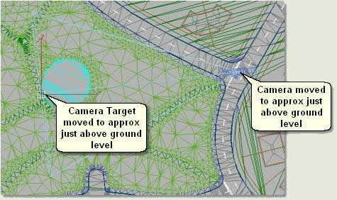
- Open Key 3D Camera
 and press Pick Camera
 - Pick the camera in the Top viewport. This configures the camera for use with Key 3D Image Objects and mini-renderers

Note that the camera is renamed Camera_Key3D
- Right click in the Left viewport and type C on the keyboard to change the view to the Camera view. Note also that the name is evident in the top left of the viewport and that Camera_Key3D is now displayed on the button. This shows that a camera has been configured for use as the Key 3D Camera

7.2 Setup views
- Select the Camera Target in the Top viewport
- Open Key 3D Move Over
 and press Selected. The name Camera_Key3D.Target appears under Object and a yellow border displays that this is the object that will move over the surface
 - Change the Z Distance to 1. This places the camera target 1m above the surface
NOTE: Sometimes the object has to be moved slightly in the Top viewport before a reading is given in the Z Height spinner
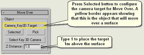
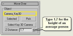
- Repeat this process for the Key 3D Camera
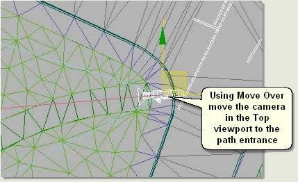
- In the Top viewport move the Key 3D Camera to the path entrance
- Open Key 3D View Manager
- Press Save Camera View. In the Save View dialog type Entrance 01 and then Save
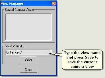
- The view appears in the Mini-Renderer and View list
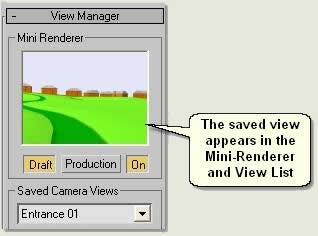
- Repeat the above procedure for all the entrance points so that 4 named views are created
- Finally, move the camera target to the centre of the site - where the small play area meets the path - and move the camera up to give an overview of the site
- Create 4 more views named Overview SW, Overview SE, Overview NW and Overview NE to make 8 views in all
- Press Browser to open the View Manager Browser
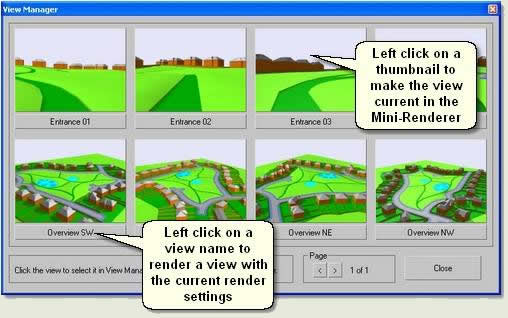
- Left click on a view name to render the view with the current render settings
- Left click on a thumbnail to make the view current in the Mini-Renderer
- To change the view in the viewport to the same as the Mini-Renderer press Copy to Camera
Donate to CADTutor
If you found this tutorial useful, you might like to consider making a donation. All content on this site is provided free of charge and we hope to keep it that way. However, running a site like CADTutor does cost money and you can help to improve the service and to guarantee its future by donating a small amount. We guess that you probably wouldn't miss $5.00 but it would make all the difference to us.
The Basics
- Dual Dimensions in a Dim…
- UCSICON Options
- "Best of" Basics: Irreg…
- Tool Palette Basics
- Original Dimension Value
- Possible Solutions to th…
- Avoid Using 'Standard' i…
- Shorten the Plot Scales…
- Update the Source File B…
- User Increment Angles fo…
- Drawing Information
- 'Sign Language'
- Rotate with the Copy Opt…
- Use the INSERT Osnap on…
- To or From the Current L…


