

Stage 2: Create Landform Mesh
Introduction
The final type of data needed when creating a 3D scene from AutoCAD is groundmodel data. This is traditionally kept in a number of ways in AutoCAD: Levels / Contours / Triangular mesh / 3D Grid / 3D polylines (strings)
The groundmodel data we use here is a combination of Key Levels and 3D Splines. This stage explains the process of using Key Levels and creating 3D splines (called 3D polylines in AutoCAD) and creating a spline model for the whole site, including both design and site context geometry. The spline model is then turned into a terrain object to form a landform mesh (the terrain object joins the vertices of the spline model to form a mesh). It is this site landform mesh which is used in the next stage (Stage 3) to create separate surfaces using the 2D surface boundaries
NOTE: This tutorial presumes that no AutoCAD 3D data is available apart from key levels. Often, as part of infrastructure design, 3D AutoCAD design data (usually 3D strings) is available and can be used as part of this modelling process
2.1 Import boundaries, and create 3D splines
The next step is to import the boundaries and detach and make copies of those splines that are to be used to create the 3D spline model
- Open MAX/VIZ and make sure Key 3D Template is used (Ref 1.1)
- File > Import. Choose Files of Type: AutoCAD(*.DWG, .DXF) and select Project for 3D 03.dwg
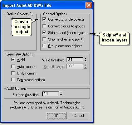
- On the AutoCAD DWG/DXF Import dialog > Layers Tab check Select from list and tick all the layers prefixed with 'B_'. These are all the boundary layers
- On the Geometry Tab > Derive AutoCAD Primitives by > Layer is selected and just Weld is checked to a threshold of 0.1
- Press Ok to import the boundary lines
The boundary lines will now be used for two elements of the 3D model:
1. Production of a 3D spline model for conversion to a Terrain object
2. For cutting the landform mesh to produce separate 3D surface meshes for road, pavement grassed areas etc
- Firstly, rename all the objects in the Modify Panel, removing the prefix 'Layer:'
To create the splines to be used for the production of the 3D spline model do the following:
Copy and rename the road boundary line
- Select the 'B_Road' object
- Edit > Clone - select Copy and press Ok - This creates a copy and keeps the copy selected. Rename the copy: 3Dspline_Road
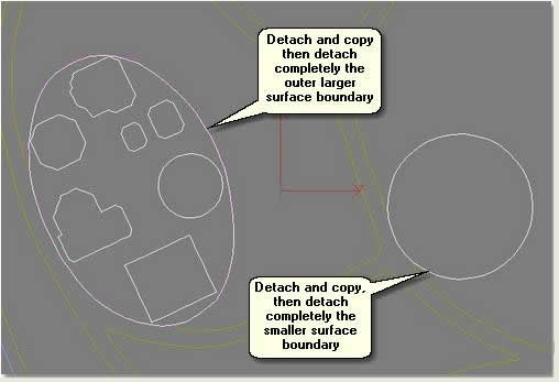
Detach, copy and rename the play boundary lines
- Select the 'B_Play' object
- In Spline sub-object mode detach (copy) the larger surface boundary and name 3Dspline_Play 01 and detach (copy) the smaller play surface boundary and name 3Dspline_Play 02
- Still in Spline sub-object mode detach (detach completely ie do not copy) the larger surface boundary and name Layer:B_Play 01 and detach (detach completely ie do not copy) the smaller surface boundary and name Layer:B_Play 02
- Exit sub-object mode
Detach, copy and rename the grass boundary lines
- Select the 'B_Grass' object
- In Spline sub-object mode detach (copy) each surface boundary and name B_Grass 01 and B_Grass 02 etc untill all seven boundaries have been detached and renamed
Note: The original 'B_Grass' object will consist of just one boundary when six boundaries have been detached and this can simply be renamed 'B_Grass 07'
- Select each grass boundary in turn and copy clone each, renaming the copies 3Dspline_Grass 01, 3Dspline_Grass 02 etc untill all have been copied and renamed
- Exit sub-object mode
Rename the context boundary
- Finally, rename the B_Context object to 3Dspline_Context. This spline will only be used to create the terrain
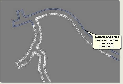
2.2 Detach pavement boundaries
- Select B_Pavement
- Isolate Selection
- In Spline sub-object mode select each spline and detach, renaming the detached splines B_Pavement 01, B_Pavement 02 etc
- Exit sub-object mode
- Exit Isolate Selection
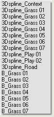
The following objects should now be in the scene:
NOTE: This stage could be by-passed as Key 3D surfacing routines can cut and surface multiple boundaries, but because there are few boundaries it is prudent to separate them
2.3 Interpolate splines and create a terrain
This process builds a 3D spline model from which to create a MAX/VIZ Terrain object for the overall site landform
- Hide all objects apart from those with prefix 3Dspline...
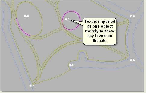
Import level text
- Keep in the current scene or open ACAD to 3D Stage 2a.max
- Open AutoCAD and Project for 3D 03.dwg
- Turn Off all layers except G_Levels
- Save the drawing
- In MAX/VIZ use the Legacy AutoCAD Import dialog to import the text (using Merge on the first dialog) and use the following settings:
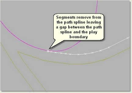
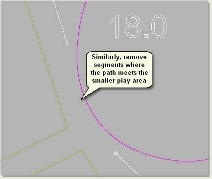
Remove segments not needed to form the landform mesh and move 'flat' area boundaries to the correct level
- Remove segments from splines that overlap other splines, for instance where the play areas touch the paths. Remove segments from the grass boundaries in segment sub-object mode
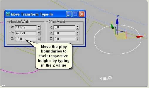
- Maximise the User viewport and move 3Dspline_Play01 and 3Dspline_Play02 to the height shown on the level text within the boundaries
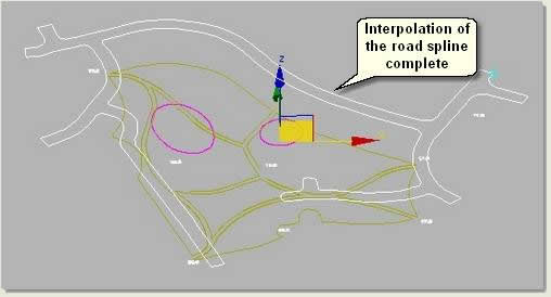
Interpolate the Road spline
- In the User viewport select 3Dspline_Road01 and open Key 3D Interpolator

- Under Options make sure Turn Snaps On/Off and Display Snap Settings are checked
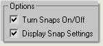
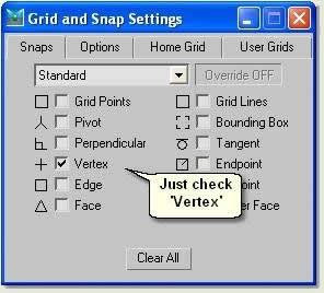
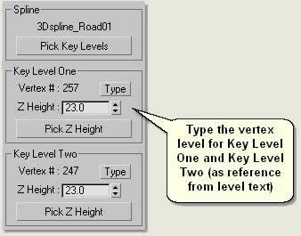
- Press Pick Key Levels. Vertex numbers will display and the Snaps Settings dialog appears
- Just check Vertex and close the dialog
NOTE: Display Snap Settings can be unchecked once this has been set
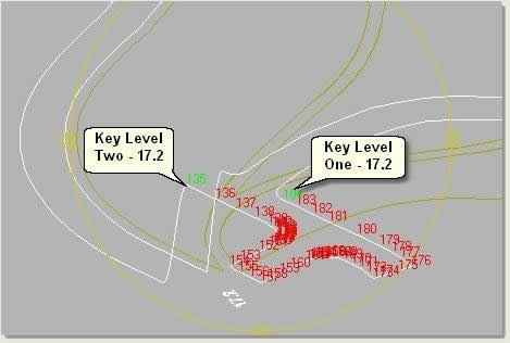
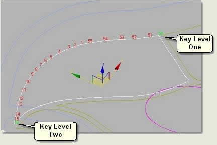
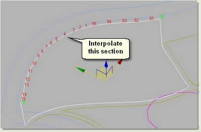
- Zoom to the area of road shown below and hover the cursor over vertex 257 (this may be different depending on the number of vertices added). Look at the Interpolator rollout whilst doing this and when 257 appears under Key Level One left click. The level is then entered and Interpolator is ready to enter Key Level Two
- Hover the cursor over vertex 247 (again this will differ from the example shown) and left click when displayed under Key Level Two.
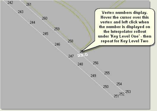
When Key Level Two is recorded then the buttons on Interpolator become active. Also, the numbers for the key levels turn green in the viewport and vertex numbers to be interpolated turn red. Only the vertices on one side of the key levels are displayed in red - these are the vertices marked for interpolation
- Type in the level of each vertex. In this case both levels are 23
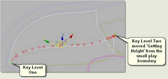
The Key Level vertices jump to their correct heights:
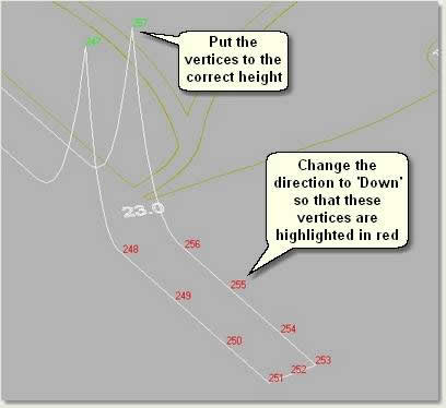
- Practice changing the direction Up or Down before leaving the direction on Down as shown
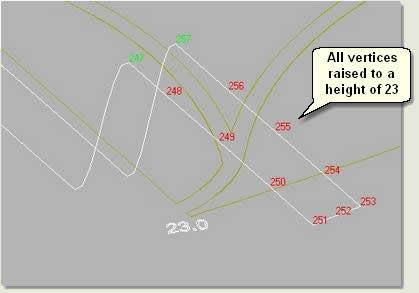
- Press Interpolate - this interpolates all vertices between the key levels. In this case, all levels are moved to a height of 23
- Press Pick Key Levels again to repeat the process for the next section of spline
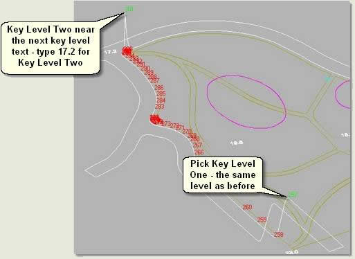
- Change the direction Up or Down as required, then press Interpolate
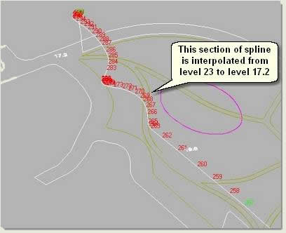
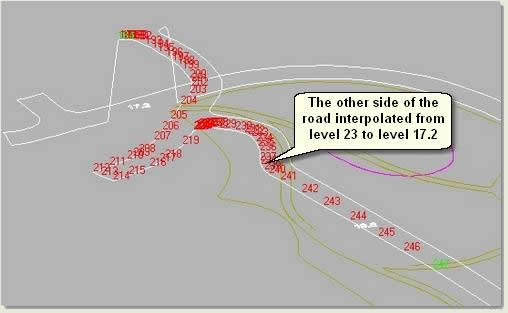
- Repeat this procedure on the other side of the road as shown below
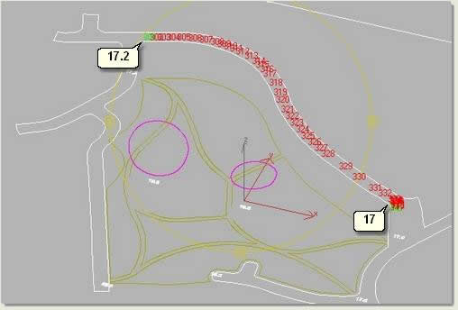
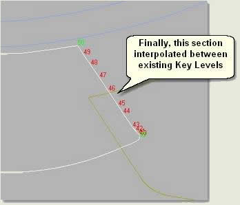
- Interpolate the next section which is flat at a height of 17.2
- Interpolate the next section (both sides) from 17.2 to 17
- Complete the interpolation of the road spline as above using the level text as reference
NOTE: If part of a spline is interpolated wrongly eg if it is interpolated up instead of down, Undo will not work. To correct mistakes the spline will need re-interpolating. Save the scene regularly (sequential saves using Save As + button is a good habit also) to minimise having to do this
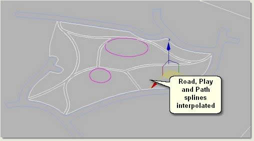
Interpolate the path slines
The path splines are interpolated similarly, however levels can be automatically picked up from other splines that have been interpolated (road spline or other interpolated path splines) or put to height (play area flat boundaries). This will speed the process up as you interpolate more splines
- Select the spline shown on the image below
- Select key levels as shown
- Repeat the process for all path splines, checking with 'Arc Rotate Selected' that the lines represent smooth and accurate path edges
- Finally, attach the path splines to create one editable spline and delete the level text
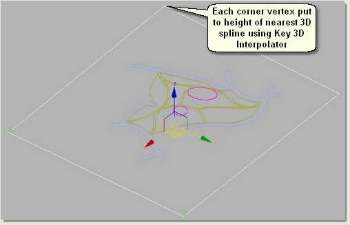
Interpolate the Context Spline
The site needs a context landform. This stops the site 'floating' in mid air and is useful to apply aerial imagery or other context data
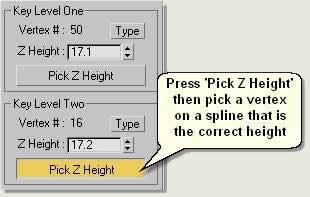
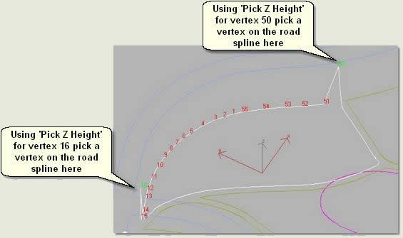
- Interpolate the Context spline using Key 3D Interpolator - Use Get Z Height buttons to get height of vertices on the nearest 3D splines. Although no height data is available in this case, this will give an approximation of height
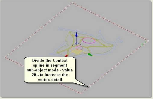
- To complete the 3D spline model divide the Context spline in segment sub-object mode to give more vertex detail
Create a Terrain
- Attach all the splines together
- Finally create a Terrain object from the splines: Key 3D Surfaces dropdown menu > Terrain

TIP: To view the terrain and validate the road, path and play surfaces use the Facets + Highlights display mode
- Finally, convert the Terrain to an Editable mesh (select, right click and 'Convert to Editable Mesh') and rename Landform
- Hide the landform mesh
Donate to CADTutor
If you found this tutorial useful, you might like to consider making a donation. All content on this site is provided free of charge and we hope to keep it that way. However, running a site like CADTutor does cost money and you can help to improve the service and to guarantee its future by donating a small amount. We guess that you probably wouldn't miss $5.00 but it would make all the difference to us.
Local Navigation
Sponsored Links

The Basics
- Dual Dimensions in a Dim…
- UCSICON Options
- "Best of" Basics: Irreg…
- Tool Palette Basics
- Original Dimension Value
- Possible Solutions to th…
- Avoid Using 'Standard' i…
- Shorten the Plot Scales…
- Update the Source File B…
- User Increment Angles fo…
- Drawing Information
- 'Sign Language'
- Rotate with the Copy Opt…
- Use the INSERT Osnap on…
- To or From the Current L…


