

Loft Mapping
Introduction
This tutorial follows on from the simple Loft tutorial in 'Creating Objects' and uses a different sample file
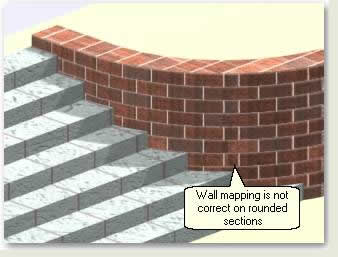
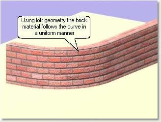
The illustration below demonstrates what happens when a brick material is assigned to a rounded wall created by extruding a closed spline. The mapping is 'Box'. Although sometimes this can be acceptable at a distance the bricks elongate around rounded corners and do not follow the curve correctly
Download Sample Data
kf410_files.zip (513kb)
module_4_maps.zip (5.2mb)
- Open kf410_01.max to view the problem with mapping textures round curves when extrusions are used instead of lofts
Prepare the Loft Path
As explained in previous tutorials, when using tiled materials on geometry that curves around corners, using the Loft Compound Object is usually the best solution. The mapping can be made to respect the curve. For infrastructure and landscape projects this technique is relevant to objects such as kerbs, retaining walls and wall copings
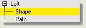
The Loft Compound Object extrudes a 'Shape' object along a 'Path' object. Lines from AutoCAD can be used, even if brought in as closed polygons (2D plan walls are usually drawn as closed polygons and it is useful to use this data without re-drawing)
- Open kf410_02.max This file contains two wall polygons from AutoCAD and a rectangle object created in MAX/VIZ
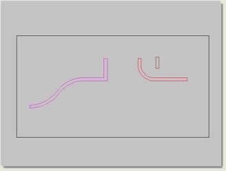
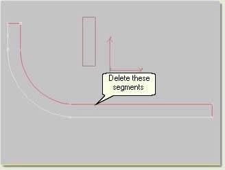
- In segment sub-object mode select the segments on the inner side of the walls and delete. A spline and not a closed polygon is needed for the loft path
Create the Wall Loft
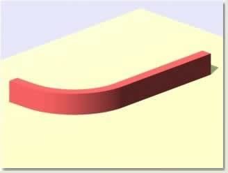
The resulting wall lines will form the 'paths' for lofting a wall 'section'. The wall section is the rectangle object Wall section. A simple rectangle is used here to demonstrate how the wall height and width can be changed parametrically after the loft has been created
- Select Wall 01 spline
- Create Panel > Geometry > Compound Objects > Loft
- Creation Method rollout > Get Shape
- Select Wall section. The resulting loft forms the wall. Select the loft and rename it Wall 01 lofted
Modify the Loft Shape Position
After creating the loft it will be necessary to modify the position of the section on the path spline. At present the rectangle is positioned so that it is lofted along its pivot point. This is the default lofting position. The pivot point on the shape object could be altered to the bottom corner of the rectangle. However, in this example the loft parameters are going to be used to adjust the rectangle's position
- Select Loft 01 and in the Modify Panel change its name to Wall loft 01
- Modify Panel > Loft > Sub Object > Shape
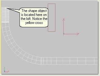
- In the top viewport move the cursor to where the yellow cross was positioned and notice the cursor changes to a cross. Left click while the cursor is in this position to make the Shape Commands rollout active (they turn from greyed out to black text). These commands automatically position the shape around the path line

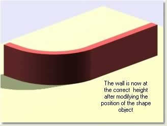
- Maximise the user viewport and press Top button, then the Left button. Notice that the shape and the wall moves up to its correct position. Experiment moving the shape around the path line before putting it back to its correct position. Finally in the modify list click Shape to come out of sub-object mode
Change the Shape Object
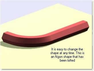
- Draw an Ngon approximately the same height as the rectangle next to the rectangle
- Select Wall loft 01
- Modify Panel > Creation Method rollout > Get Shape button. Leave the Instance radio button selected. In the viewport select the Ngon and right click to finish the command. The wall is now an Ngon loft. Repeat the process for re-positioning the shape on the loft before changing the shape back to the rectangle and re-positioning it
Modify Loft Skin Parameters
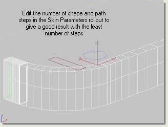
It will always be necessary to change the amount of steps on the shape and the path to alter the complexity of the loft. In general, the loft should just contain the appropriate amount of shape and path steps to give a good result. A common mistake in lofting is leaving far too many path and shape steps
- Modify Panel > Skin Parameters rollout. Set the spinners to 0 and 10
Modify Loft Shape Parameters
When the loft was created, the default setting when selecting the shape was to use it as an instance. This means that when the shape parameters are changed, the changes will then be passed on to the wall
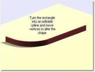
- Select Wall section (the rectangle). In the Modify Panel change the length and width of the rectangle and notice how the wall's width and height changes. There is a problem here though as the height and width are altered from the default central pivot point of the rectangle. To solve this, select the rectangle, open the Hierarchy Panel under 'Pivot' press Affect Pivot only. Use endpoint and pivot snaps to snap the pivot to the bottom left corner of the rectangle. Right click to come out of the command then with the rectangle selected right click over it and turn to editable spline
- Select the wall loft and re-apply the rectangle shape which is now an editable spline. The shape should position itself on the path exactly how it should do without re-positioning it
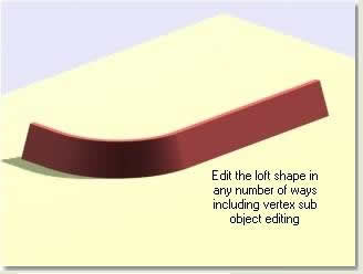
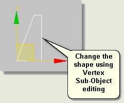
- Select Wall section rectangle again and change its length and width by going to vertex sub object mode and moving the vertices up or across with the transform gizmo. The wall will change height and width, but this time will stay in the correct place
When the shape is wrong way round on the loft
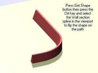
Often, with irregular shapes for kerbs etc the shape appears on the wrong side. To flip the shape on the path:
- Select the loft, press Get Shape button then press the Ctrl key and select Wall section spline in the viewport
NOTE: This operation cannot be reversed in the same manner. Undo must be used straight away if the section needs to be flipped back to the original position
Optimise the Loft Path if necessary
Often loft paths are positioned accurately in AutoCAD and the use of arcs is common (and indeed recommended). However, the use of arcs can produce non-uniform path steps along a loft and lead to an inappropriate number of faces
- Open kf410_03.max
- Select Wall loft 01 and right click over it to look at its properties and ascertain how many faces it consists of. With 0 shape steps and 12 path steps the wall has 548 faces. For a small wall this is quite a load on the scene. To optimise the wall loft the type and number of vertices on the loft path may need editing thus:
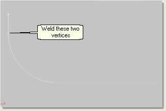
- Select Wall 01 path spline and Isolate Selection. In the top viewport notice that the spline only has 6 vertices and that two of these are very close together
- In vertex sub-object mode select the two vertices close together and press Weld on the Geometry rollout
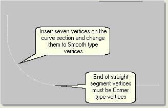
- Go to segment sub-object mode and press Refine button. Move the cursor over the spline and insert 7 vertices on the curve. The spline now has 12 vertices
- Still in vertex sub-object mode select all the vertices on the curve, exluding the vertices at the end of the straight segments (these need to be Corner vertices). Right click over a red selected vertex and select Smooth from the vertex type quad menu
- Similarly, turn all the other vertices into Corner vertices
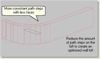
- Come out of sub-object mode and Exit Isolation. The wall loft now has more even path steps
- Select the wall loft and in the Modify Panel change the path steps to 0. Notice that the number of faces has been reduced to 84 without a dramatic reduction in quality. If necessary, increase the number of path steps to 1
Assign a Brick Material to the Wall and Adjust the Mapping using the Loft Parameters
- Open kf410_04.max
- Select Wall loft 01
- In the Material Editor select 'Brick for loft' material and assign to selection
- In the Modify Panel adjust the loft mapping under Surface Parameters rollout to Length repeat: 0.6 and Width repeat: 0.4. Notice that the bricks are not stretched or 'odd' like an extruded wall with a UVW Map Modifier applied. The bricks follow the curve in the wall in a uniform manner
Repeat with the other wall and unhide the steps
- Select Wall 02 spline, assign the brick material and adjust the loft mapping
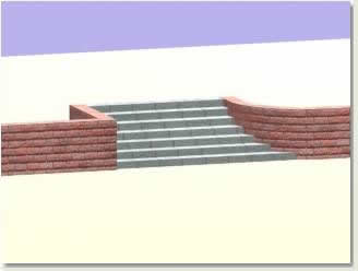
- Finally, in the Display Panel unhide all to reveal pre-created steps and render
After experimenting with the extensive parameters of the loft object and mapping options revisit the tutorial scene to apply materials to the loft objects that form edges
- Open kf410_05.max. This follows on from the previous tutorial
Walls
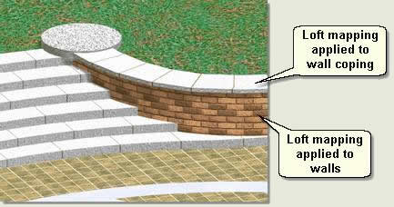
- Assign Bricks for loft material to Wall loft left and Wall loft right then use the loft mapping parameters to map the bricks as they would appear in real-world
Wall coping
- Assign step blocks tilesmap material to Wall coping left loft and Wall coping right loft and modify accordingly. Increase the path steps if necessary to achieve a smoother curve and better mapping
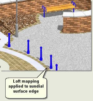
Sundial surface edging
- Assign Edging sundial surface material to Sundial surface edge loft and modify accordingly
TIP: This tutorial names materials often according to the objects they are being assigned to. In practice it is good policy to name materials pertaining to their properties eg 'Light Concrete' or 'Red Brick Edging'. Then you can save and re-use the materials in other scenes
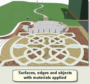
- Finally, assign Wall ends material to Wall ends to complete the application of materials to surfaces, edges and objects
Donate to CADTutor
If you found this tutorial useful, you might like to consider making a donation. All content on this site is provided free of charge and we hope to keep it that way. However, running a site like CADTutor does cost money and you can help to improve the service and to guarantee its future by donating a small amount. We guess that you probably wouldn't miss $5.00 but it would make all the difference to us.
Local Navigation
Sponsored Links
The Basics
- Dual Dimensions in a Dim…
- UCSICON Options
- "Best of" Basics: Irreg…
- Tool Palette Basics
- Original Dimension Value
- Possible Solutions to th…
- Avoid Using 'Standard' i…
- Shorten the Plot Scales…
- Update the Source File B…
- User Increment Angles fo…
- Drawing Information
- 'Sign Language'
- Rotate with the Copy Opt…
- Use the INSERT Osnap on…
- To or From the Current L…


