
Selection Methods
Introduction
Keeping track of and selecting objects in a scene is a crucial part of 3D modelling. Develop a good strategy for naming, selecting, grouping and displaying objects before embarking on a project. This should start in AutoCAD by using a comprehensive layer strategy for 3D conversion
This section explores the main selection and organisational tools available in MAX / VIZ thus:
Naming Objects
Viewport Selection Methods
Selection Sets Groups
Display Options
Download Sample Data
kf202_files.zip (959kb)
module_2_maps (5.9mb)
Naming Objects
You can name objects as part of the creation process and by selecting them and re-naming in the Modify Panel. Once named, you can select any object by its name using the Select by Name dialog
Name on Creation
- Open kf202_01.max. This simple scene contains a box (at 0 height), some trees, bollards, lighting and seats
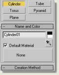
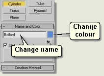
- Create Panel > Geometry > Cylinder Draw a cylinder as a simple bollard. Notice when created the cylinder is auto-named Cylinder01 Before creating the cylinder change the name in the Name Box to Bollard
- Change the colour by clicking the colour swatch before creating a cylinder in the scene at the appropriate parameters
Name after Creation
- In kf202_01.max select one of the cylinders in a circle
- Modify Panel > Name Box (top) Change the name to Bollard 01
Select by Name
- Main Toolbar > Select by Name dialog Select Box01 > Select Change the name Box01 to Ground
- Main Toolbar > Select by Name dialog Practice selecting objects in the scene using this dialog
TIP: Apart from the normal use of the Ctrl and Shift keys to select single or multiple entries in list boxes, MAX / VIZ enables you to left click and drag the cursor down a list to highlight entries
Rename Dialog
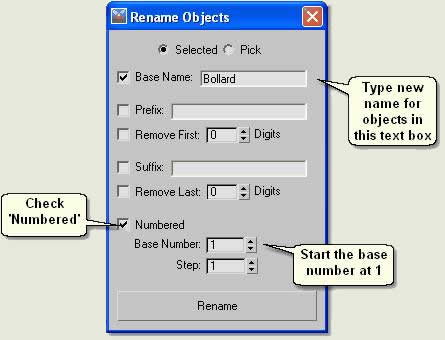
- Menu Bar > Tools > Rename
- Select objects to rename
- Type the new name for the objects in the Base Name text box
- Check Numbered to auto-number the objects and change the Base Number to 1
- Press Rename to automatically rename the objects
Viewport Selection Methods
Selecting objects in 3D is a little more complex than in 2D. As well as using the Select by Name dialog, become familiar with the following selection tools for selecting objects directly in the viewports
- Open kf202_01.max if not already open .
- Main Toolbar > Select Object
 The button turns orange meaning you are in selection mode
 - In the viewport move the cursor over objects and notice that pop-up labels showing the name of objects appear in the viewport as you hover over objects

- To select an object move the cursor over it. If an object is selectable then the arrow cursor changes to a cross. Left click to select it
- When selected the object will show selection brackets (default white) and also a pivot marker (default red) in Smooth + Highlights display mode and will turn white with a pivot marker in Wireframe display mode . This is how you know an object, or objects are selected. Practice selecting in each display mode
- Also notice that when selected the name of the object appears on the top line of all panels in the Command Panel apart from the Create Panel where it is shown further down. If multiple objects are selected then 'x' objects selected appears instead
Selecting objects overlapping other objects
- Sometimes, one object is positioned over or below other object/s. In the scene, recreate this by arc rotating so that a seat, lighting column and bollard or tree are all in line with each other in the User viewport
- Place the cursor over a point over where the objects overlap
- Keep left clicking and notice that the objects are selected in turn
Using Selection Regions
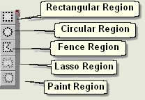
- Main Toolbar > Region button flyout > Rectangular region
- In the viewport left click and drag a rectangular region around all objects to be selected. This is a crossing window ie all objects crossing the window will be selected
NOTE: MAX has another button ![]() that toggles between window and crossing window selection modes when using these region selection tools. Window selection mode means that only objects entirely enclosed by (and not crossing) the window will be selected
that toggles between window and crossing window selection modes when using these region selection tools. Window selection mode means that only objects entirely enclosed by (and not crossing) the window will be selected
- Main Toolbar > Region button flyout > Circular region
- In the viewport left click and drag a circular region around all objects to be selected. This is a crossing window ie all objects crossing the window will be selected
- Main Toolbar > Region button flyout > Fence Selection Region
- In the viewport keep left clicking to describe a polygonal selection region around objects that need selecting. Double left click to select the objects. Again, this is a crossing window ie all objects crossing the window will be selected
- Main Toolbar > Region button flyout > Lasso Selection Region
- In the viewport keep the left click button and move the mouse to describe a polygonal selection region around objects that need selecting. Unclick the left mouse button to select the objects
- Main Toolbar > Region button flyout > Paint Selection Region
- In the viewport left click and move the paint circle over objects that need selecting
NOTE: The Selection Filter dropdown on the Selection Tools enables you to filter types of objects for selection
Selection Sets
Selection Sets are a handy way of selecting objects and naming the 'set' so that you can select this selection set from a list to select the objects again
- Open kf202_01.max if not already open
- Select all the trees
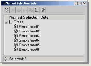
- Main Toollbar > Named Selection Sets Type 'Trees' into the text box then pres Return
![]()
- Deselect the trees by left clicking in a blank space
- Main Toolbar > Named Selection Sets From the dropdown list select 'Trees' Notice that all the trees have been selected as before
To Edit Named Selection Sets
- Main Menu > Edit > Edit Named Selections
- Practice adding and deleting objects from selection sets and explore the other available buttons. These are easy to understand
Groups
Grouping holds objects together and is used mainly to reduce the amount of objects in a scene. If you have 250 trees in a scene, for example, cosider grouping these together to form one group called 'Trees'. In this way they will not hinder selection of other objects in the Select by Name dialog
- Open kf202_01.max if not already open
- Select all cylinders in the scene
- Main Menu > Group In the Group dialog type Bollard blocks > OK
- Notice that you can now select the group as if it was one object. Also, in the Select by Name dialog notice that the Bollard blocks group is enclosed in brackets and is at the top of the list. In the Command panel the name 'Bollard blocks' is in bold
To Ungroup
- Select the group
- Main Menu > Group > Ungroup The group is split up into the original objects
To Open and Close a Group
- Select (Bollard blocks)
- Main Menu > Group > Open This allows you to edit any object within the group. Select one or two cylinders and either delete or move them into new positions (covered later). Notice that the selection brackets still cover the whole group
- Make sure at least one object in the group is selected
- Main Menu > Group > Close This closes the group
To Detach an Object
- Open the group and select an object
- Main Menu > Group > Detach this detaches the object / s from the group
To Attach an Object
- Open the group and select an object or objects that are not part of the group, but you want to include in the group
Main Menu > Group > Attach this Attaches the object / s to the group
NOTE: In general it is advised that for landscape objects such a seats, lighting columns etc grouping is not used to pull together different parts of the objects. The Attach command should be used instead and a multi/sub-object material used to apply different materials to different parts of the object
TIP: When moving multiple objects to a known point group them before the move and ungroup them after the move. Otherwise, all the objects' will be moved to the new point by their own pivot point position and the spacial relationship between all the objects will be lost
Display Options
Use the Display Panel to elect to display or not display objects in the viewport. This is an invaluable aid when modelling, not least to help you concentrate on just those objects that needs editing without having the 'clutter' of other objects in the viewport
- Open kf202_02.max. This scene contains similar objects to the last, but with a sunlight system and a camera on a path. Render the Camera viewport to get a feel for the scene and move the time slider to see the camera animate around a camera path (circle object called 'Campath))
- Display Panel > Hide (Off in VIZ) by Category rollout Check the following categories On whilst looking at the Top viewport
- Geometry - all geometry is hidden
- Shapes - the circle called Campath is hidden
- Lights - the Omni Lights and Sunlight system are hidden
- Cameras - the camera is hidden
- Helpers - the Sunlight compass is hidden
- Display Panel > Hide (On/Off in VIZ) rollout The buttons in this rollout are self-explanatory. Practice selecting objects and using these buttons to Hide or unhide objects in many ways
- Display Panel > Freeze (Lock in VIZ) rollout Freezing objects means that they cannot be selected. Although not as extensively used as Hide (or On/Off) these display tools can be used to 'blank' various objects from the scene
- Finally, look at a very useful tool called Isolate Selection. Select one or two objects in the scene:
- Main Menu > Tools > Isolate Selection The objects are isolated, the rest of the objects in the scene being hidden. On screen the following dialog appears:
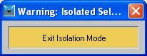
- Press Exit Isolation to restore the previous display
Donate to CADTutor
If you found this tutorial useful, you might like to consider making a donation. All content on this site is provided free of charge and we hope to keep it that way. However, running a site like CADTutor does cost money and you can help to improve the service and to guarantee its future by donating a small amount. We guess that you probably wouldn't miss $5.00 but it would make all the difference to us.
Local Navigation
Sponsored Links
The Basics
- Dual Dimensions in a Dim…
- UCSICON Options
- "Best of" Basics: Irreg…
- Tool Palette Basics
- Original Dimension Value
- Possible Solutions to th…
- Avoid Using 'Standard' i…
- Shorten the Plot Scales…
- Update the Source File B…
- User Increment Angles fo…
- Drawing Information
- 'Sign Language'
- Rotate with the Copy Opt…
- Use the INSERT Osnap on…
- To or From the Current L…


