

 Michael’s Corner #90
June 2010
The AutoCAD® Workbench is Now Shipping!
It is our collective pleasure to announce that, by the time of the posting of this month's Michael's Corner, The AutoCAD Workbench is on its way to dozens of you! Those of you who have already sent in payment will be first to receive your copy. I'm really pleased with how it turned out and I hope you are, as well. Over 200 pages, 300+ "How To" exercises, and fully indexed. I think the most humbling emails I received was from a reader in Sao Paulo who said he could now dispense with the loose-leaf copies he had made of assorted articles, now that it was all going to be in one volume!
Download the Order Form which has all the relevant information for purchasing either the book, the .PDF, or a combination of both. You will also find options to use PayPal on the Workbench page of my website.
This month's articles are included in The AutoCAD Workbench, so order your copy today!
…Adding a Sub-Panel to a panel on the Ribbon
…PDF Underlay layers
…Tab through commands and variables
…The BLOCK and INSERT commands
And I want to give a shout out to my class at NeoCon, too. On Wednesday, June 16th I will be presenting my 8th annual ‘AutoCAD Toolbelt’ session at the NeoCon Worlds Trade Fair at the Merchandise Mart in Chicago. I'm looking forward to another great class of very appreciative professionals, some of whom are kind enough to sign up each year!
If you would like to contact me directly, you can do that also.
Blessings to one and all,
Michael
Adding Another Row to a Panel on the Ribbon
 It's time to take our Ribbon customization up a notch, so I figured we could customize a panel to have more than just a single string of commands. This question came up in my recent training at ethos in Phoenix as we were heading to lunch. I hadn't really investigated it before, but the three of us figured it out, so I wanted to pass it along.
Before you begin, you may want to review the fundamentals of adding a tab and a panel to the Ribbon that was covered in Michael's Corner in August 2009.
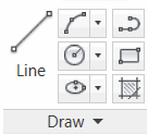
To understand what we're aiming for, on the Draw panel [Home tab] you see a large icon for the Line command, then three additional rows of more commands. How do they do that? The three rows are called ‘Sub-panels’, and here's how it works.
How to Edit the Appearance of the Tools on Your Tab
Open the CUI.
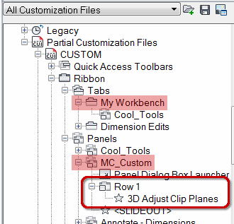
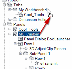
Expand Partial Customization Files, expand CUSTOM, expand Ribbon, then expand Panel. In this exercise, I have a Tab named My Workbench and a Panel named MC_Custom. (The Cool Tools panel is what I developed in the exercises in The AutoCAD Workbench.)
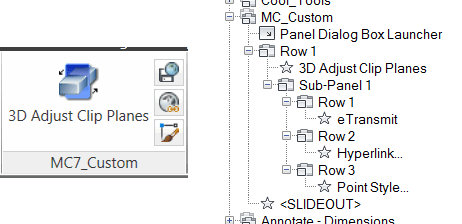
Click on the first tool in Row 1 of your custom panel (in this exercise, ‘3D Adjust Clip Plane’) to display the Properties pane on the right.
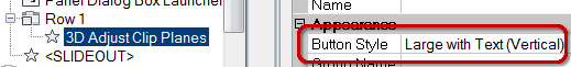
Under Appearance, click the Button Style item, then click the dropdown to display the four options.
Click Large with Text (Vertical); this is the style used by the Line command on the Draw panel.
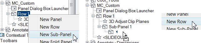
To add a ‘stack’ of tools to your customized panel, right-click on Row 1, then click New Sub-Panel and you will see Sub-Panel 1 with an unnamed node below it. That's the first row of that Sub-Panel.
Drag a command up from the Command list and release it next to the unnamed node below Sub-Panel 1.
Right-click on Sub-Panel 1, then click New Row (not Sub-Panel) to create another unnamed node.
Note: Curiously, the nodes below a Sub-panel are not numbered ‘Row 1’, ‘Row 2’, etc. until after you have closed and saved the CUI, then re-opened it.
 Add another tool to the unnamed node under the Sub-Panel. Repeat as needed.
Finally, drag your panel up and release it beside your custom tab.
Note: If you are editing a panel that is already associated with a tab, you do not need to re-assign it to that tab.
Click OK to close and save your edits to the CUI, then click your new tab to see the arrangement!
Gold Star Tip: For your reference, the two figures here are my custom Panel and the CUI that drives it.
Power Tool
PDF Underlay Layers
 If you have Adobe Acrobat or other Adobe products, you probably have an Adobe printer driver that enables you to print a .PDF from the AutoCAD Plot dialog box.
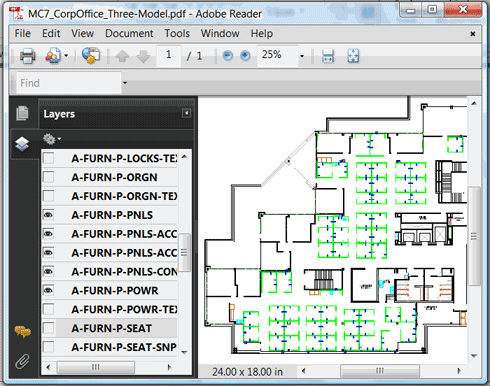
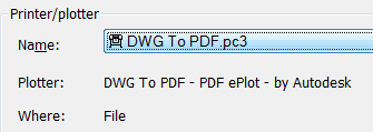
Did you know, however, that if you use the Autodesk driver - DWG To PDF.pc3 - the Adobe Reader built in to AutoCAD will immediately open and you will be able to toggle on and off layers?
Give it a try next time you need to print to a .PDF.
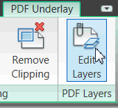
 Note: See Michael's Corner January 2010 to learn how to attach a PDF Underlay to a drawing. When you click on the attached .PDF, click the Edit Layers button on the context tab to open the Underlay Layers dialog box.
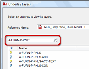
In addition to the ability to turn layers on and off in the underlain .PDF, you can also specify search criteria for the layer name. Nice.
The Odd Spot
Tab Through Commands and Variables
Enter the first few characters of a command or variable, then hit Tab to cycle through the commands and variables that start with those letters. In AutoCAD 2010 and AutoCAD 2011, enter RO, then hit Tab repeatedly and you will see the following string of commands and variables: ROAMABLEROOTPREFIX, ROLLOVERTIPS, ROTATE, ROTATE3D.
Gold Star Tip: Any command aliases you have added to ACAD.PGP are also listed as you Tab through!
The Basics
How to Create and Insert a Block
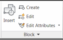 A block is, essentially, a symbol. Something you want to repeat. The Block panel on the Home tab contains the Create tool which will open the Block Definition dialog box.
The following exercise take you through the block-making basics after creating the geometry for a data and communications symbol. If you have already drawn something you want to turn into a block, go straight to Step 9, below.
How to Create a Block for a Data/Communications Symbol
Create a new layer named Electrical, give it a color, then set it to be current.
Click Polygon [Home tab
 expanded Draw panel].
For the number of sides, enter 3, then pick a point to specify the center of the polygon.
Press [Enter] to accept the default option for Inscribed <I>, then, with ORTHO On, move your cursor north, and enter 6 for the radius of the circle.
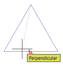
Click Line [Home tab
Draw panel], then use Endpoint snap and pick the top of the triangle as the Start point.Use Shift + right-click, then click Perpendicular and click the bottom line of the triangle, then press [Enter] to end the command.
Launch the Hatch command and set the Type to Solid.
Move into one half of the triangle, and when you see the preview, click to place the hatch. Press [Enter] to end the command.
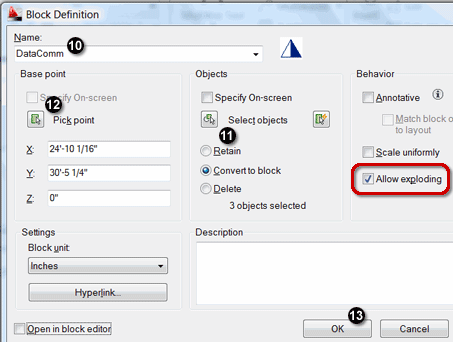
Click Make Block to open the Block Definition dialog box.
-
Enter a name for the block. In this exercise, I'll name it DataComm.
Click Select Objects, then select the geometry for the block and press [Enter].
For the Base Point of the block, click Pick Point and specify a point on the block that will essentially be the ‘handle’ you will use to insert the block. In this exercise I'm using Endpoint snap to specify the top of the triangle.
Note: Always ‘Allow Exploding’.
Click OK to complete the block-making procedure.
The Insert Command
 Although the Tool Palette is the optimum feature for inserting blocks, using the Insert command [Insert tab
![]() Block panel], you can insert a block that's already defined in the drawing.
Block panel], you can insert a block that's already defined in the drawing.
Note: When inserting a block, make sure you have the proper layer current for it to ‘land’ on.
In the following exercise, you insert a sample drawing into a blank drawing.
How to Insert a Block
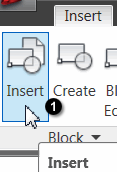
Click Insert [Insert tab
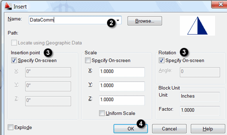
Block panel] to open the Insert dialog box.If the name of the block is not displayed in the name field, click the dropdown arrow and select your block.
The default settings to specify the Insertion point and the Rotation on-screen is usually adequate for most procedures.
Click OK to close the Insert dialog box and you will be prompted for the insertion point and the rotation for the block.
Note: To insert a .DWG, click Browse, to open the Select File dialog box.
Left Field
Chicago Trivia:
1772: A Haitian named Jean-Baptiste Pointe du Sable, a fur trader, founded a settlement called Eschikagou on the north bank of the Chicago River. (He was not officially recognized as the city's founder until 1968.)
1833: On August 12, the town of Chicago was incorporated with a population of 350.
…and it also happens to be my absolute favorite city in the United States.
Donate to CADTutor
If you found this article useful, you might like to consider making a donation. All content on this site is provided free of charge and we hope to keep it that way. However, running a site like CADTutor does cost money and you can help to improve the service and to guarantee its future by donating a small amount. We guess that you probably wouldn't miss $5.00 but it would make all the difference to us.
Note from Michael: I want to thank all of my customers for continuing to retain my training services (some for over three decades!) and let you know your donations do not go to me personally, but to the ongoing maintenance of the CADTutor ship as a whole and to support the yeoman efforts of my friend and CADTutor captain, David Watson, to whom I am grateful for this monthly opportunity to share a few AutoCAD insights.
Share this page:


The Basics
- Dual Dimensions in a Dim…
- UCSICON Options
- "Best of" Basics: Irreg…
- Tool Palette Basics
- Original Dimension Value
- Possible Solutions to th…
- Avoid Using 'Standard' i…
- Shorten the Plot Scales…
- Update the Source File B…
- User Increment Angles fo…
- Drawing Information
- 'Sign Language'
- Rotate with the Copy Opt…
- Use the INSERT Osnap on…
- To or From the Current L…


